MICROWAVE & ANTENNas
Microwave, Antennas, RF Facility
MICROWAVE AND RF Facility
MICROWAVE AND RF SUBSYSTEMS Design and Development
- EW Receivers 40 GHz
- Radars
- Filters, Attenuators, Antennas
- SAR
- Phased Antenna arrays

Clean Room - Class 100000
ANTENNA LABORATORY
MILTARY AND CIVIL COMMUNICATIONS SYSTEMS ANTENNAS FOR
-
RADAR
-
EW RECEIVERS AND JAMMERS
-
VHF/UHF/COMMUNICATION
-
AVIONIC, NAVAL, GROUND, MOBILE
| Frequency | 0.5 to 8 GHz |
| Connector Type | SMA type jack |
| Power Handling | 2 Watt c.w. |
| VSWR | 4.5:1 maximum. < 1.4 :1 above 1 GHz. |
| Gain | -6.5 to 1.4 dBiL |
| Axial Ratio | < 2 dB (above 1 GHz) |
| 3dB Beamwidth | 48 to 139 degrees |
| 10dB Beamwidth | 112 to 176 degrees |
| Squint | < 10 degrees |
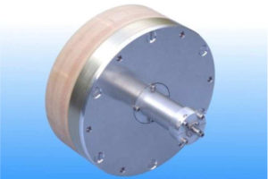
| Maximum Size | 152 mm diameter x 120 mm long |
| Weight | 570 g nominal |
| Construction | Aluminium and engineering plastics |
| Mounting |
4 holes tapped M5 x 7.5 mm deep, 137.2 mm pitch circle diameter |

Typical Antenna Gain / Factor
This is calculated by reference to standard gain horn antennas, and cross checked with reference to the antenna beamwidth, with an estimated error of +/- 0.8dB.
Patterns measured using a linear source antenna , Horizontal / Vertical refers to the polarisation of the source horn.
On patterns the Red & Black trace = Horizontal polarised source, Green & Blue trace = Vertical polarised source
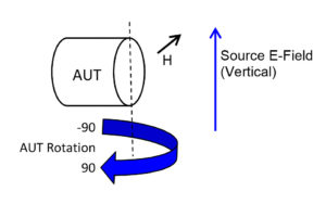
Pattern Cut Definition
Patterns are measured using a linear source antenna. The polarisation refers to the electric field polarisation of the source antenna.
Horizontal Cut (Cut 1) Vertical Cut (Cut 2)
Antenna viewed from back
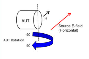
- Red trace = Sweep with horizontal source polarization and antenna under test in horizontal cut (cut 1)
- Blue trace = Sweep with vertical source polarization and antenna under test in horizontal cut (cut 1).